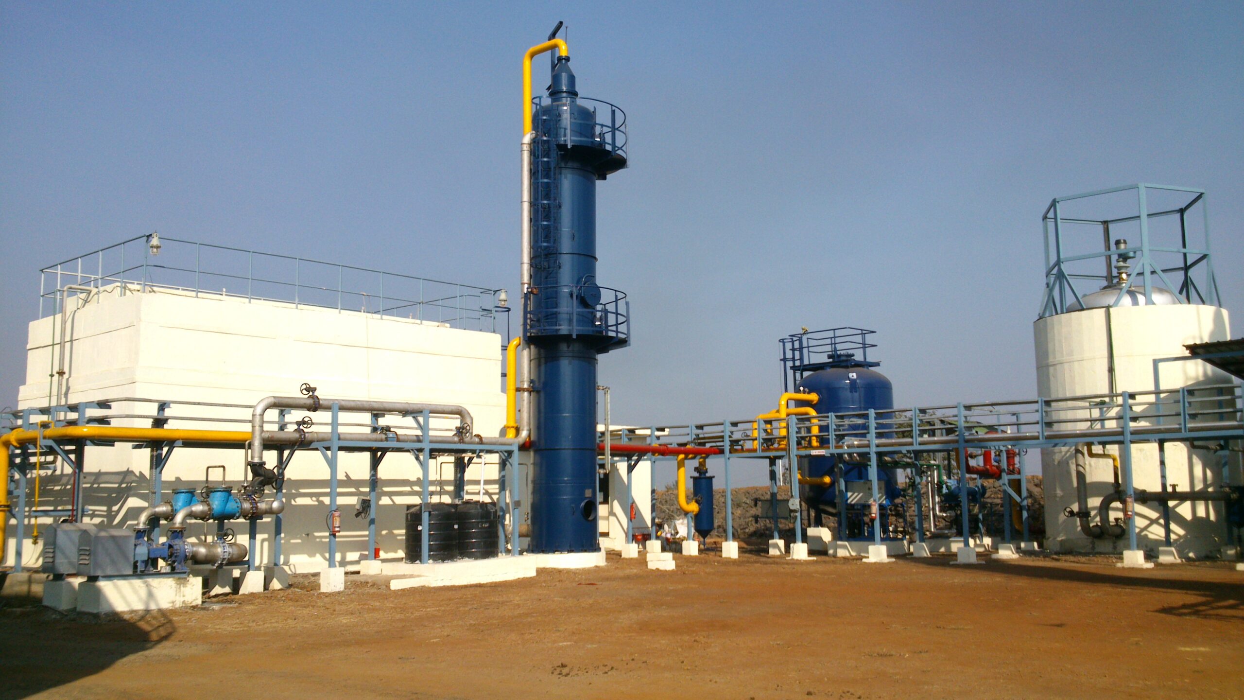

“CO2 SkrubberTM System
This system uses a pressurized water scrubbing technology offered by IETL for carbon dioxide removal and scrubbing of varied gas streams such as biogas, landfill gas, sour natural gas, unconventional gas streams such as Coal Bed Methane (CBM), shale gas as well as vent gas/tail gas & acid gas streams.
The system is consisting of:
LP Compressor
- Removal of CO2 from Biogas by absorption process involving the use of scrubbing medium (i.e., water in this case) or Membrane System or PSA system.
- Regeneration of scrubbing medium (i.e. water) by employing an Air Stripping Technique.
- Drying of clean gas for further application.
-
CO2 removal system is described as below:
Pressurized Water Scrubber
After pressurization of the biogas, carbon dioxide is removed in a scrubber / absorber. The scrubber is packed with packing material for excellent mass and heat transfer. In the absorber carbon dioxide is removed by scrubbing. The recirculation water is fed into the absorber at the top, while the biogas flows through the absorber counter current to the water.
Regeneration of Scrubber water
This is achieved by method of Air Stripping. In the air stripping tower air coming from outside is put into a desorption reactor where the recirculation (scrubber) water is counter currently flowing down. Most of the CO2 is removed by stripping to the atmosphere.
-
Pressure Swing Adsorption (PSA)
In PSA processes, biogas is compressed to a pressure between 0.5-2 barg and is fed to a vessel (column) where it comes in contact with a adsorbent that will selectively retain CO2. The adsorbent is a porous solid, normally with high surface area. We have considered zeolite bed adsorbent. The purified CH4 is recovered at the top of the column with a very small pressure drop. After certain time, the adsorbent is saturated with CO2, and the column needs to be regenerated by reducing the pressure (normally to vacuum for biogas upgrading). Multi-column arrays are employed to emulate a continuous process. One of the most important properties of the PSA process is that is can be adapted to biogas upgrading in any part of the world since it does not depend on the availability of cold or hot sources.
In PSA system methane loss is approx. 5-10%. Depending on the service adsorbent zeolite will require replacement every year.
-
Membranes
The use of membranes for gas cleaning is a well-established technology in chemical industries. The membrane is a porous material that let some gases permeate through its structure. Employing an adequate material, it is possible to have selectivity between the gases of the mixture to be separated. For this particular application, two different streams are obtained: a permeate gas (mainly CO2, water and ammonia) and the retentate (concentrated CH4). The most commonly employed materials are hollow fibers made of different polymers. In this process, the biogas is compressed to 12-16 bars and then routed to a two-stage membrane process where methane with purity higher than 96% is produced.
-
Treated Biogas Balloon:
Treated Biogas from CO2 removal system is sent to Treated Biogas Balloon for storage. Treated Biogas Balloon shall have biogas blowers, air blowers, level indicators, inbuilt flow control mechanism of blower as applicable, level transmitter, adequate standard safety feature, gas sampling point, necessary instruments, monitoring & control facility, safety instruments, piping, blinds & valves and auxiliary facilities.
-
Flare System:
Provision of flare system is considered to burn the popup/released bio-gas from the gas purification/gas storage section. The pilot burner will be kept on continuous basis as a source of ignition. The flare system shall have flare (enclosed type), flare burners with associated instruments, pilot burners system along with all safety system, spark ignition device/FFG (Flame Front Generator), LPG Cylinder along with regulators, all piping, valves, electrical conduit, thermocouple wiring, all instrumentations required for safe & reliable operation, monitoring & control systems, alarms, interlock and auxiliary facilities.
-
Pressurization of Upgraded Biogas and Storage (Treated Biogas Compressor):
Treated biogas stored in balloon is subsequently compressed to pressure of maximum 250 bar (g) by a high-pressure compressor and routed to priority panel. Priority panel shall allow compressor to direct gas to the Compressed Gas Metering Skid. Treated Biogas compressors shall have KOD, inter/after coolers, electrical motor drives, One CBG Storage vessel along with required instrumentation, monitoring & control facility, safety instruments, piping, blinds & valves and auxiliary facilities.
-
CBG Cascade Bottling System:
Treated biogas from CO2 removal system is routed to Treated Biogas balloon and subsequently compressed to maximum 250 Barg pressure passing through metering skid and shall be transferred to cascade bottling system. The CBG cascade bottling system shall have 20 nos. of cascade (each cascade should contain approx. 40 cylinders each of capacity 75 water litres), all equipment related to gas cascade system, cylinder bank, other related accessories, all instruments, safety instruments, metering & control system, piping, blinds & valves and auxiliary facilities.
-
Integrated SCADA & Control System
A dedicated PLC (Redundant CPU, Communication & Power) based system with SCADA for the complete plant shall be used for operation and control of the plant.
SCADA shall provide single operator window for monitoring & control of the plant. PLC shall also integrate the inherent safety and shutdown signals for safe shutdown of the facility based on the process cause & effect diagrams.


